Case study: Ahmed body
End-to-end validation from a single natural-language input to a four-mesh family, with drag and lift converging toward wind-tunnel measurements.
The Ahmed body is a simplified car shape that has been a standard benchmark for automotive CFD since the 1980s. We use the 35° rear slant configuration, which produces a fully separated wake behind the slant. Wind-tunnel measurements report drag coefficient CD = 0.279 and lift coefficient CL = 0.004.
VortexAI generated a family of four meshes at increasing resolution (1.5M, 4.5M, 12M, and 27M cells). The only user input was a natural-language description:
No refinement regions, no cell sizes, no meshing parameters. All of that is determined automatically by the agent chain.
How the system reasons about the flow
This is where VortexAI differs most from template-based approaches. The physics agent analyzes the geometry and flow conditions, then identifies the regions that need targeted mesh refinement. These regions are not prescribed by the user. They emerge from the agent's reasoning. Here is what the physics agent produces for the Ahmed body (all quotes are verbatim LLM output):
The agent also identifies junction vortices at the support stilts (regions F, G) and extends a wake cascade several body lengths downstream (region I) with a dedicated ground-refinement region (J).
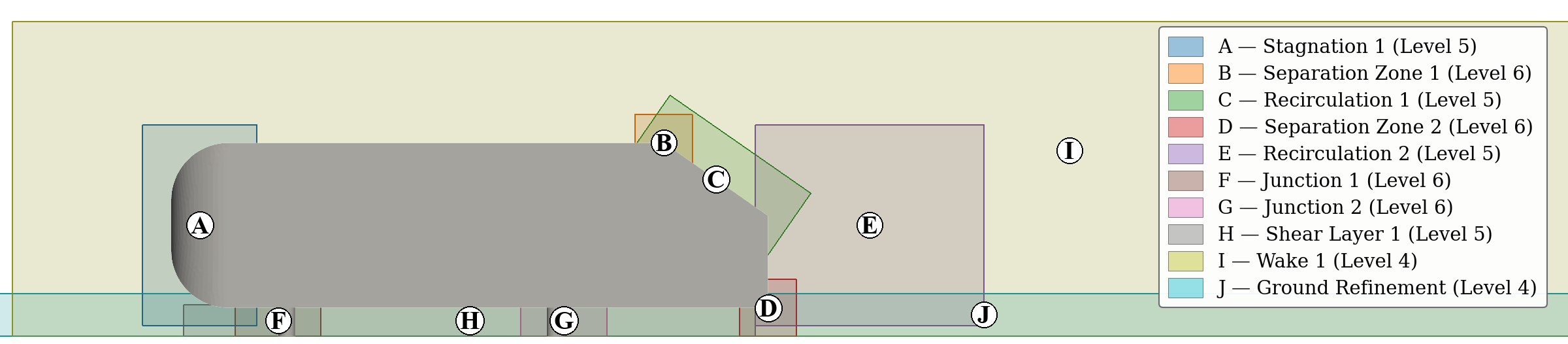
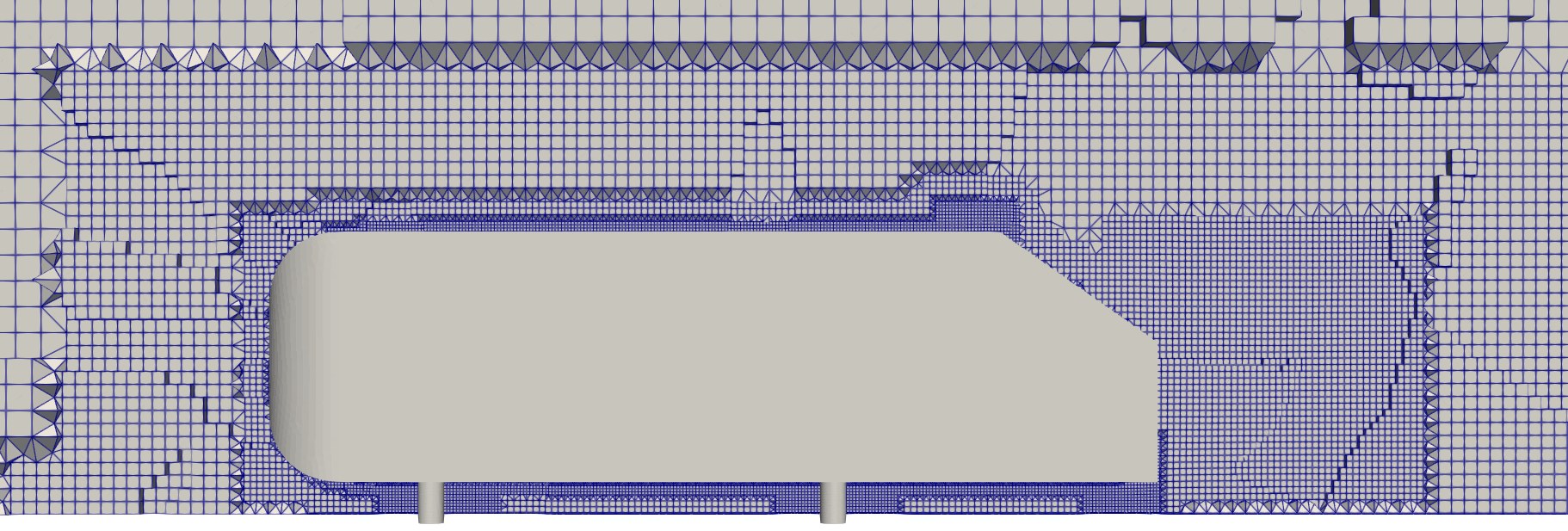
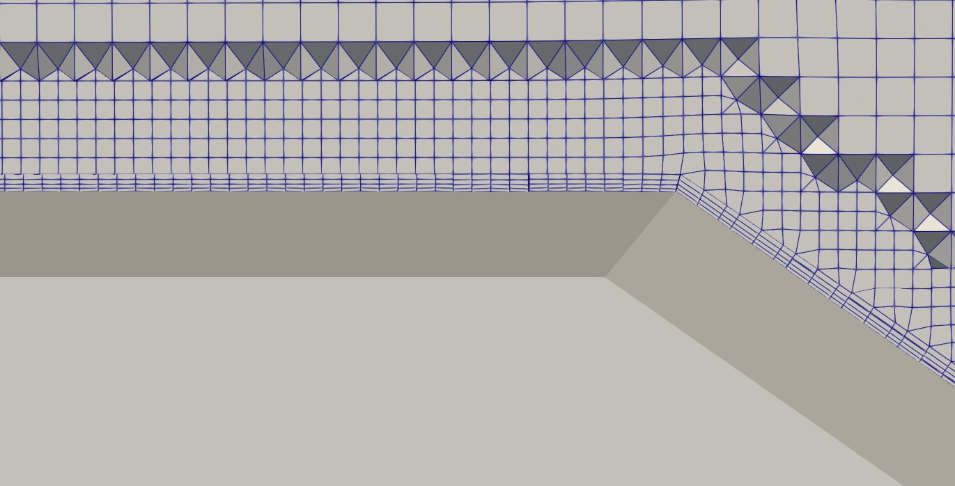
The strategy agent then translates these regions into a conforming octree hierarchy. The vehicle surface is refined to level 7 (2 mm cells), with smooth transitions through levels 6 and 5. Boundary layers consist of six prism layers with a first-cell height of 0.356 mm, targeting y⁺ = 50 for the wall-function formulation.
Validation against wind-tunnel data
Each mesh is passed to VortexAI's simulation pipeline, which sets up a steady-state RANS case (simpleFoam, k–ω SST, wall functions). The results are compared against the experimental measurements of Lienhart et al. (2003).
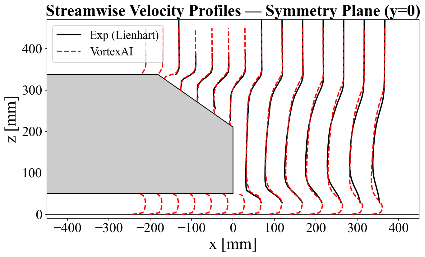
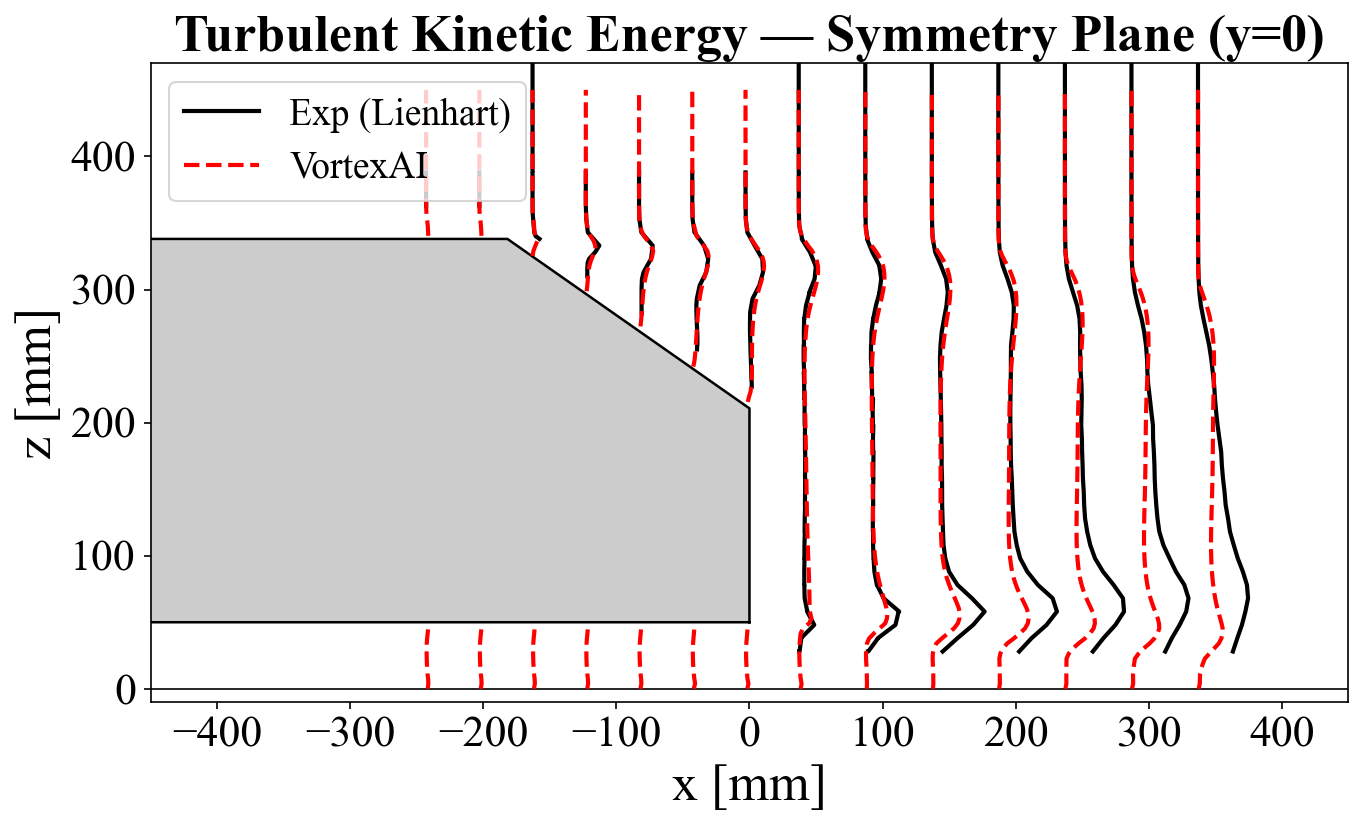
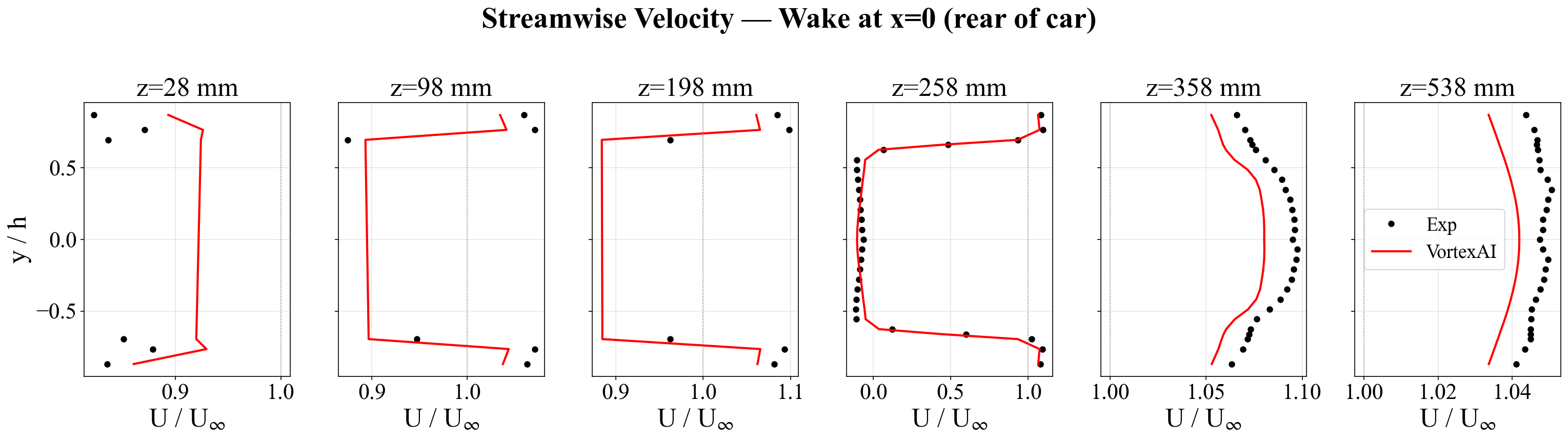
Velocity and turbulence. The boundary-layer development over the roof, the separation at the slant, and the wake recovery are all captured. The main discrepancy is in the far wake, where the simulation slightly underpredicts velocity. This is a known limitation of steady RANS with k–ω SST on bluff bodies, not a mesh quality issue.
Grid convergence. The drag coefficient decreases monotonically with refinement, approaching the experimental CD = 0.279. Richardson extrapolation to zero mesh spacing lands close to the experimental value. The lift coefficient shows more scatter, which is expected for a quantity sensitive to the steady-state assumption. A published RANS reference on a 22M-cell mesh reports CD = 0.300, above the VortexAI predictions for the 5M+ meshes.
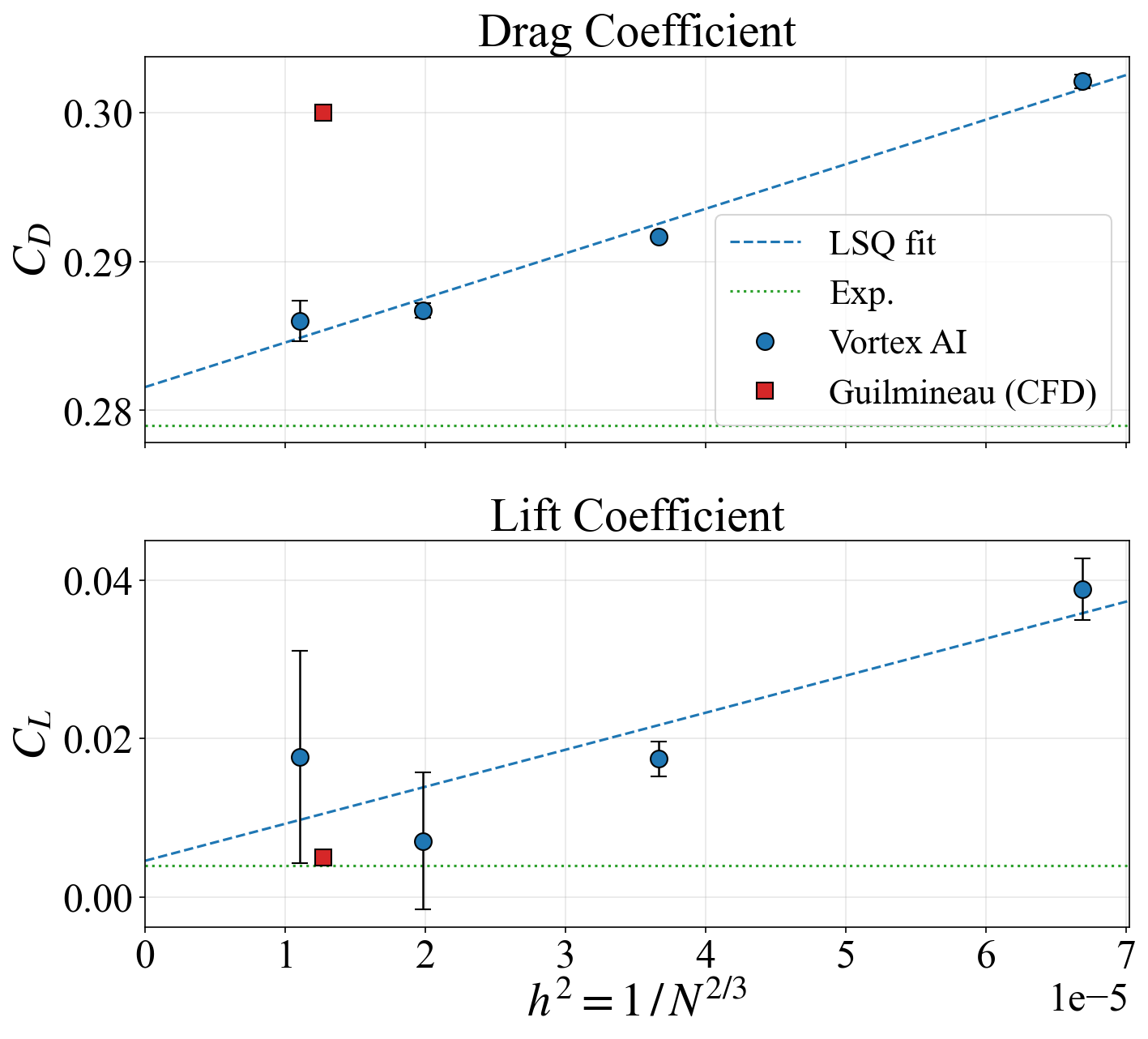
The bottom line. VortexAI-generated meshes produce aerodynamic predictions that converge toward experimental data with increasing resolution, with no manual tuning of meshing parameters.